Linux virtual interfaces introduction
Contents
Introduction
In this post I will give a brief introduction for all commonly used virtual
interfaces. There is no code analysis. Only brief introduction and the usage
on Linux. So anyone with a network background could have a look at this
blog post. The interface list can be obtained with the command ip link help.
The first part is some frequently used interfaces and some interfaces that can be easily confused with one another. The second part will be a brief introduction of all kinds of tunnels(TBD).
Bridge
What is a bridge
A linux bridge behaves like a network switch. It forwards packets between interfaces that are connected on it. It’s usually used for forwarding packets on routers, gateways, or between VMs and network namespaces on a host. It also supports STP, VLAN filter and multicast snooping.
When to use a bridge
When you want to establish communication channels between VMs, containers and your hosts.
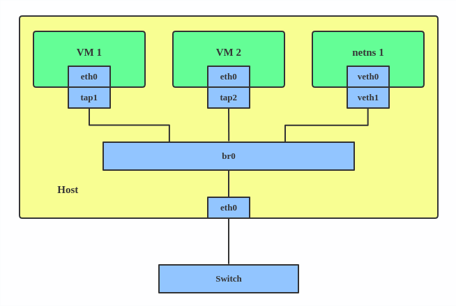
How to create a bridge
| |
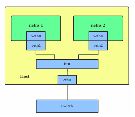
This creates a bridge device named br0 and set two tap devices(tap1, tap2), a veth device(veth1) and a physical device(eth0) as its slaves, as shown in the picture.
Bonding
What is bonding
The Linux bonding driver provides a method for aggregating multiple network interfaces into a single logical “bonded” interface. The behavior of the bonded interfaces depends on the mode; generally speaking, modes provide either hot standby or load balancing services.
When to use bonding
When you want to increase your link speed or do failover on your server.
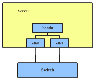
How to create a bond
| |
This creates a bond interface named bond1 with mode active-backup. For other modes, please see: Kernel bonding doc
Team
What is team
Similar to bonding, the purpose of the team device is to provide a mechanism to team multiple NICs (ports) into one logical one (teamdev) at L2 layer.
The main thing to realize is that the Team project is not trying to replicate or mimic the bonding driver. What it does is to solve the same problem using a different approach, using e.g. lockless (RCU) TX/RX path and modular design.
But there are also some functional difference between bonding and team. e.g. team supports LACP load-balancing, NS/NA (IPV6) link monitoring, D-Bus interface, etc., that are absent in bonding. For further details about the differences between bonding and Team, see: Bonding vs Team.
When to use team
When you want to use some features that bonding doesn’t provide.
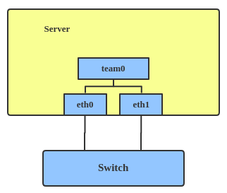
How to create team
| |
This creates a team interface named team0 with mode active-backup, and adds eth0, eth1 as team0’s sub-interfaces.
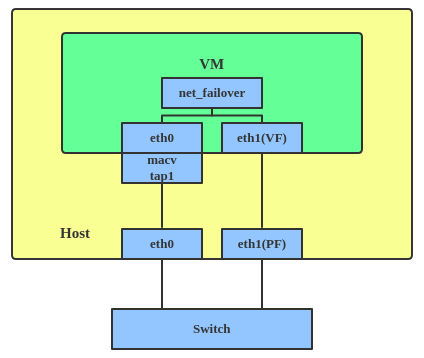
More info: a new driver called net_failover has been added to linux recently. It’s another failover master netdev for virtualization and manages a primary (a passthru/vf device) and standby (the original paravirtual interface) slave netdevs.
VLAN
What is VLAN
VLAN, aka virtual LAN. It separates broadcast domains by adding tags to network packets. VLANs allow network administrators to group hosts under the same switch or between different switches.
The VLAN header looks like: 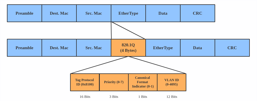
When to use VLAN
When you want to seperate subnet in VMs, namespaces or hosts
How to create VLAN
| |
This add VLAN 2 with name eth0.2 and vlan 3 with name eth0.3. The topology
looks like: 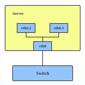
Note: When configuring a VLAN, you need to make sure the switch connected to the host is able to handle VLAN tags, e.g. by setting the switch port to trunk mode.
VXLAN
What is VXLAN
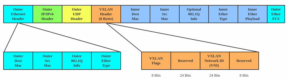
VXLAN(Virtual eXtensible Local Area Network) protocol is a tunnelling protocol designed to solve the problem of limited VLAN IDs (4096) in IEEE 802.1q. It is described by IETF RFC 7348.
With a 24-bit segment ID, aka “VXLAN Network Identifier (VNI)”, VXLAN allows up to 2^24(16 777 216) virtual LANs, which is 4096 times of VLAN capacity.
VXLAN encapsulates Layer 2 frames with a VXLAN header into a UDP-IP packet, which looks like:
When to use VXLAN
VXLAN is typically deployed in data centers on virtualized hosts, which may be spread across multiple racks.
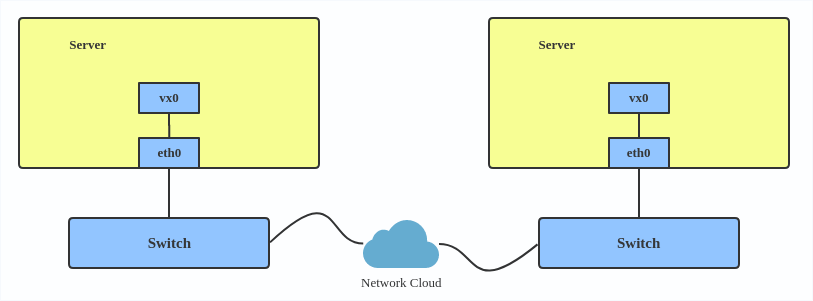
How to create vxlan
| |
For reference, you can read the vxlan kernel doc or an other vxlan introduction
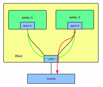
MACVLAN
What is MACVLAN
With VLAN, we can create multiple interfaces on top of a single one and filter packages based on VLAN tag. With MACVLAN, we can create multiple interfaces with different Layer 2 (i.e. Ethernet MAC) addresses on top of a single one .
Before MACVLAN, if users wanted to connect to physical network from VM or namespace, they would have needed to create TAP/VETH devices and attach one side to bridge, and attach a physical interface to the bridge on the host at the same time.
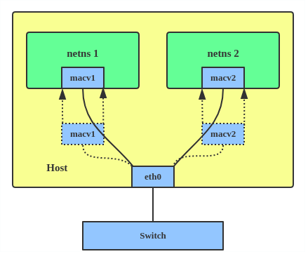
Now, with MACVLAN, they can bind a physical interface, associated to a MACVLAN, directly to namespaces, without the need for a bridge.
There are four MACVLAN types:
Private: doesn’t allow communication between MACVLAN instances on the same physical interface, even if the external switch supports hairpin mode.
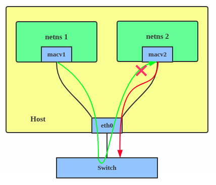
VEPA: data from one macvlan instance to the other on the same physical interface is transmitted over the physical interface. Either the attached switch needs to support hairpin mode, or there must be a TCP/IP router forwarding the packets in order to allow communication.
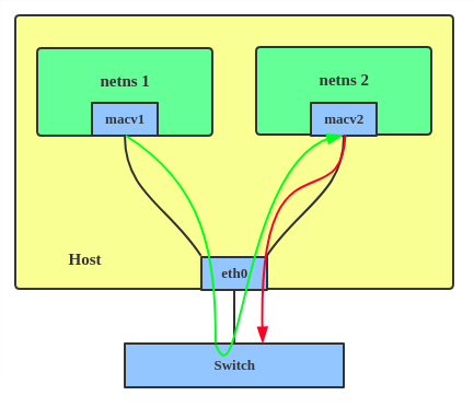
Bridge: all endpoints are directly connected to each other with a simple bridge via physical interface.
Passthru: allows a single VM to be connected directly to the physical interface.
Source: the source mode is used to filter traffic based on a list of allowed source MAC addresses, to create MAC-based VLAN associations. Please see the commit message
The type is chosen according to different needs. Bridge mode is the most commonly used
When to use MACVLAN
Users want to connect directly to physical network from Containers.
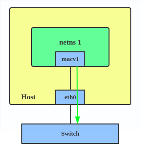
How to setup MACVLAN
| |
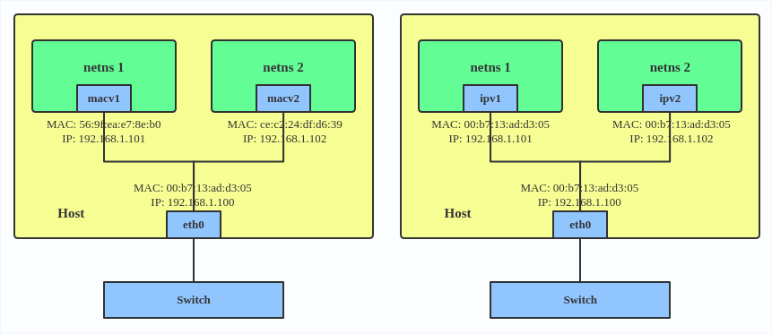
This creates two new MACVLAN devices in bridge mode. And assigns these two devices to two different namespaces.
IPVLAN
What is IPVLAN
IPVLAN is similar to MACVLAN with the difference being that the endpoints have the same mac address.
IPVLAN supports L2 and L3 mode. IPVLAN L2 mode acts like a MACVLAN in bridge mode. The parent interface looks like a bridge or switch.
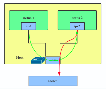
In IPVLAN l3 mode, the parent interface acts like a router and packets are routed between endpoints, which gives better scalability.
When to use IPVLAN
- Quoting the IPVLAN kernel doc
- MACVLAN and IPVLAN are very similar in many regards and the specific use
case could very well define which device to choose. if one of the following
situations defines your use case then you can choose to use ipvlan -
- The Linux host that is connected to the external switch / router has policy configured that allows only one mac per port.
- No of virtual devices created on a master exceed the mac capacity and puts the NIC in promiscuous mode and degraded performance is a concern.
- If the slave device is to be put into the hostile / untrusted network namespace where L2 on the slave could be changed / misused.
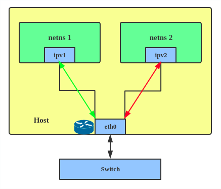
How to setup IPVLAN
| |
This creates an IPVLAN device named ipvl0 with mode L2, assigned to namespace ns0.
MACVTAP/IPVTAP
What is MACVTAP/IPVTAP
MACVTAP/IPVTAP is a new device driver meant to simplify virtualized bridged networking. When a MACVTAP/IPVTAP instance is created on top of a physical interface, the kernel also creates a character device /dev/tapX to be used just like a TUN/TAP device, which can be directly used by KVM/QEMU.
with MACVTAP/IPVTAP, we can replace the combination of TUN/TAP and bridge drivers with a single module.
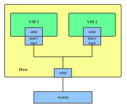
When to use MACVTAP/IPVTAP
Typically, this is used to make both the guest and the host show up directly on the switch to which the host is connected. The difference between MACVTAP and IPVTAP is same with MACVLAN/IPVLAN.
How to create MACVTAP
| |
MACsec
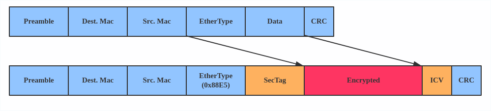
What is MACsec
MACsec is an IEEE standard for security in wired Ethernet LANs. Similiar to IPsec, as a layer 2 specification, MACsec can protect not only IP traffic, but also ARP, neighbour discovery, and DHCP. The MACSEC headers looks like
When to use MACsec
The main use case for MACsec is to secure all messages on a standard LAN, includeing ARP, NS and DHCP message.
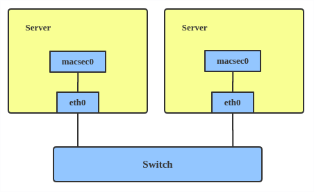
How to setup MACsec
| |
Note: This only adds a MACsec device macsec0 on interface eth1. For more detailed configurations, please see the “Configuration example” Section in MACsec introduction by Sabrina
VETH
What is VETH
This device is a local Ethernet tunnel. Devices are created in pairs.
Packets transmitted on one device in the pair are immediately received on the other device. When either device is down the link state of the pair is down.
When to use VETH
When namespaces need to communicate to the main host namespace, or between each other.
How to setup VETH
| |
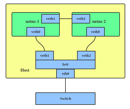
This creates two namespaces net1, net2 and a pair of veth devices, and assigns veth1 to namespace net1, and veth2 to namespace net2. These two namespaces are connected with this veth pair. Assign a pair of IP addresses, and you can ping and communicate between the two namespaces.
VCAN
What is VCAN
Similar to the network loopback devices, VCAN offers a virtual local CAN (Controller Area Network) interface, so users can send/receive can message via VCAN interface. CAN is mostly used in the automotive field nowadays.
For more CAN protocol information, please refer to kernel can doc
When to use CAN
When you want to test a CAN protocol implementation on the local host.
How to create VCAN
| |
VXCAN
what is VXCAN
Similar to the veth(virtual ethernet) driver, vxcan(Virtual CAN Tunnel) implements a local CAN traffic tunnel between two virtual CAN network devices. When creating a vxcan, two VXCAN devices are created as a pair. When one end receives the packet it appears on its pair and vice versa. VXCAN can be used for cross namespace communication.
When to use VXCAN
When you want to send CAN message across namespaces.
How to setup VXCAN
| |
IPOIB
What is it
IPOIB a device to support IP-over-InfiniBand protocol. This transports IP packets over InfiniBand so you can use your IB device as a fast NIC.
The IPoIB driver supports two modes of operation: datagram and connected. In datagram mode, the IB UD (Unreliable Datagram) transport is used. In connected mode, the IB RC (Reliable Connected) transport is used. Connected mode takes advantage of the connected nature of the IB transport and allows an MTU up to the maximal IP packet size of 64K.
For more details, please see ipoib kernel doc
When to use
When you have an IB device and want to communicate with a remote host via IP.
How to create
| |
nlmon
What is nlmon
nlmon is a netlink monitor device
When to use nlmon
When you want to monitor system netlink messages
How to create nlmon
| |
This creates a nlmon device named nlmon0 and sets it up. Use a packet sniffer (e.g. tcpdump) to capture netlink messages. Recent versions of wireshark feature decoding of netlink messages.
Dummy
What is Dummy
The dummy interface is entirely virtual, like e.g. the loopback interface. The purpose of dummy driver is to provide a device to route packets through, without actually transmitting them.
When to use Dummy
It was used to make inactive SLIP address look like a real address for local programs. Nowadays it’s mostly used for testing and debugging.
How to create Dummy
| |
IFB
What is IFB
The IFB (Intermediate Functional Block) driver supplies a device that allows concentration of traffic from several sources, and shaping incoming traffic instead of dropping it.
When to use IFB
When you want to queue and shape incoming traffics.
How to create an IFB interface
IFB is an alternative to tc filters for handling ingress traffic, by redirecting it to a virtual interface and treat is as egress traffic there.You need one ifb interface per physical interface, to redirect ingress traffic from eth0 to ifb0, eth1 to ifb1 and so on.
First, add ifb interfaces.
| |
And redirect ingress traffic from the physical interfaces to corresponding ifb interface. For eth0 -> ifb0:
| |
Again, repeat for eth1 -> ifb1, eth2 -> ifb2 and so on, until all the interfaces you want to shape are covered.
Now, you can apply all the rules you want. Egress rules for eth0 go as usual in eth0. Let’s limit bandwidth, for example:
| |
Ingress rules for eth0, now go as egress rules on ifb0 (whatever goes into ifb0 must come out, and only eth0 ingress traffic goes into ifb0). Again, a bandwidth limit example:
| |
The advantage of this approach is that egress rules are much more flexible than ingress filters. Filters only allow you to drop packets, not introduce wait times, for example. By handling ingress traffic as egress you can setup queue disciplines, with traffic classes and, if need be, filters. You get access to the whole tc tree, not only simple filters.
For more IFB qdisc use cases, please refer to: Linux Foundation wiki - IFB
Author Hangbin Liu
LastMod 2019-09-18 (d761a5f)